3/2, 5/2 or 5/3 Pneumatic Valve: How to Choose the Right One
The 3/2, 5/2 and 5/3 are the three most common directional control valves in pneumatic machine design — and they are also the most frequently misspecified. This guide explains what each one does, when to use it, and which mistakes to avoid before the order is placed.
Kanchan Rajput
Marketing Executive · May 2026
Reading the Notation
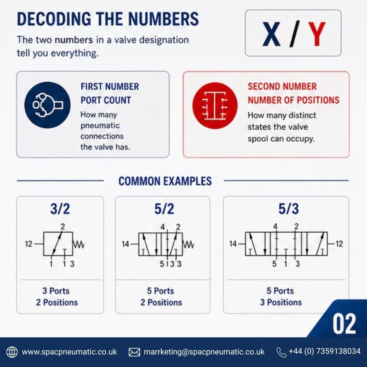
Every directional control valve is described by two numbers separated by a slash. The first number is the port count — how many pneumatic connections the valve body has. The second is the position count — how many distinct switching states the spool can move between. That is the entire notation. Once you understand it, the part number tells you everything about the valve's basic function.
Port count
The total number of pneumatic connections on the valve body — supply, actuator outputs, and exhaust ports combined.
Position count
The number of distinct switching states available. A 2 means the spool moves between two positions. A 3 adds a centre position.
What it means in practice
A 5/2 has five ports and two positions. A 5/3 has five ports and three positions. The port count stays the same — it is the number of spool positions that changes the valve's capability.
The 3/2 Valve: Simple, Reliable, Single-Direction
Three ports, two positions
P · A · R — one actuator port, one exhaust
When the valve is energised, supply pressure at port P connects to the actuator port A and drives the cylinder forward. De-energise it and port A vents to exhaust. A return spring does the rest. Clean, simple and inexpensive to run.
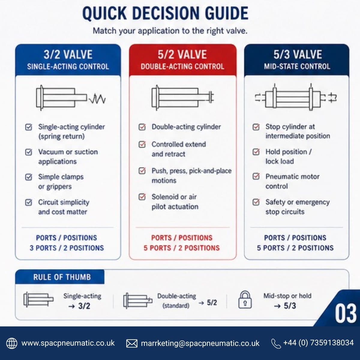
A 3/2 is the right choice when:
→ Your actuator is a single-acting spring-return cylinder
→ You need to control suction cups or vacuum grippers
→ A clamp or latch needs to return to a safe position on signal loss
→ Circuit simplicity and low cost are the priority
⚠️
Hard Limit
A 3/2 cannot properly control a double-acting cylinder. With only one actuator port there is no way to actively power the return stroke. If your cylinder needs drive in both directions, move to a 5/2.
The 5/2 Valve: The Industry Workhorse
Five ports, two positions
P · A · B · R1 · R2 — active drive in both directions
The 5/2 is the most common directional valve on the factory floor and it earns that position. In the first switching state, supply connects to port A and the cylinder extends while port B exhausts. Flip to the second position and supply moves to port B to retract while port A exhausts. Both strokes are actively powered.
Reach for a 5/2 when:
→ You are driving a double-acting cylinder
→ You need controlled positive motion in both directions
→ The application involves press, punch, push or pick-and-place movements
→ You are using solenoid pilot or air pilot actuation
Monostable vs Bistable
Both are 5/2 valves but they behave very differently the moment power is removed — and it is worth understanding which one your circuit actually needs.
🔁
Monostable (Spring Return)
One solenoid. When signal is lost a spring returns the spool to a defined rest position every single time. You always know exactly where the cylinder ends up. In most production environments a predictable fail state is not optional — and this is the valve that delivers it.
⏸️
Bistable (Detented)
Two solenoids. The spool holds its last position when power is removed because there is no spring pulling it back. Useful in applications where a power cycle should not move the actuator or where energy efficiency matters during long dwell periods.
The 5/3 Valve: When You Need a Middle State
Five ports, three positions
The 5/3 gives you the same extend and retract logic as a 5/2 but adds a third spool position in the centre. What happens in that centre state depends entirely on which variant you specify — and that choice has to match the application precisely.
Centre Configuration
Port Behaviour
When to Use
Closed centre
All ports blocked — cylinder locks in position
Holding a load mid-stroke or stopping a cylinder at an intermediate point
Exhaust centre
Ports A and B connect to exhaust — cylinder floats freely
Freewheeling pneumatic motors and systems that need to decompress safely
Pressure centre
Ports A and B both connect to supply — equal pressure on both sides
Balanced load holding and specific synchronisation applications
⚠️
One Thing to Watch on Pressure Centre
Putting a pressure-centre valve into the wrong circuit can cause pressure intensification. When equal supply pressure acts on both sides of a differential-area piston it creates a net force — and in the wrong setup that will damage components. Always verify your cylinder area ratio before specifying pressure centre.
Specification Mistakes Worth Avoiding
Fitting a 5/2 where a 5/3 was needed
When a machine needs a mid-stroke stop but has no 5/3 in the circuit, operators start improvising with mechanical stops and out-of-sequence solenoid firing. It works until it doesn't. If the application needs a centre state, design for it before the machine is built.
Using a monostable 5/2 without defining the fail-safe direction
A spring-return 5/2 will always go to the same position on power loss. If that means the cylinder extends into a part or toward an operator, that is a design error — not a valve fault. Before signing off on any circuit, confirm what de-energised actually means for every actuator in the system.
Treating all 5/3 centre configurations as interchangeable
Closed centre, exhaust centre and pressure centre cannot be swapped out in the field after installation. Specify the right variant based on what your cylinder needs to do in the unpowered state — and do it before the order is placed.
The Short Version
The decision comes down to three things: how many directions your actuator needs to move, whether it needs to stop mid-stroke, and what should happen when power is removed.
3/2
Single-acting spring-return cylinder or vacuum circuit
5/2
Double-acting cylinder with standard extend and retract motion — no mid-stop required
5/3
Mid-stroke stop required, motor freewheeling needed, or emergency-stop position must be defined
A Practical Stocking Strategy
Over-speccing a valve inventory wastes budget and makes maintenance harder than it needs to be. For most pneumatic machine builders a sensible stock looks something like this:
Valve Type
Coverage
Notes
5/2 monostable (spring return)
70–80%
The default choice. Covers the vast majority of standard double-acting cylinder work.
5/2 bistable (detented)
~10%
For circuits where actuator position needs to be held through a power loss.
5/3 closed centre
~10%
Where mid-stroke cylinder locking is part of the application.
3/2 NC (normally closed)
~5%
Single-acting cylinders and vacuum or suction circuits.
💡
Standardise Across Your Range
Standardise on a single port size and a single solenoid voltage across your whole range. It simplifies stock, speeds up maintenance and reduces the chance of fitting the wrong thing in a hurry.
Not Sure Which Valve You Need?
SPAC Pneumatic stocks a full range of 3/2, 5/2 and 5/3 directional control valves in G⅛, G¼, G⅜ and G½ port sizes. If you are specifying for a particular application or trying to standardise your inventory, our technical team is happy to help.
Talk to Our Technical Team →Tags